Introduction: The Battle Against Entropy
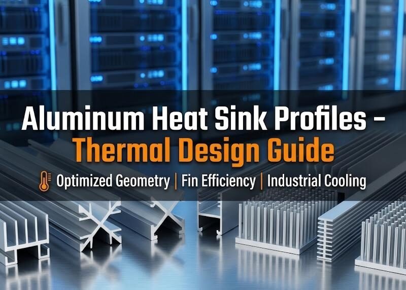
Heat is the inevitable byproduct of work. In industrial electronics—whether it’s a high-frequency VFD inverter, a massive LED array, or a CPU controlling an automation line—excess heat is the primary cause of component failure. Arrhenius Law states that for every 10°C rise in operating temperature, the life expectancy of electronic components is cut in half. To combat this, engineers rely on the passive thermal efficiency of aluminum heat sink profiles.
While copper offers superior thermal conductivity, it is heavy, expensive, and difficult to shape. Aluminum, specifically the 6000 series alloys, offers the perfect sweet spot: it is lightweight, cost-effective, and most importantly, it can be extruded into complex fin geometries that maximize surface area. This guide explores the engineering physics behind heat sink design, moving beyond basic ‘cooling fins’ to discuss boundary layer resistance, aspect ratios, and the radiative benefits of anodizing.
At Anrele, we treat thermal management as a precise science. Our capability to produce complex custom aluminum profiles allows us to create thermal solutions that fit the exact envelope of your device.
Heat Sink Profile Geometry and Airflow Optimization
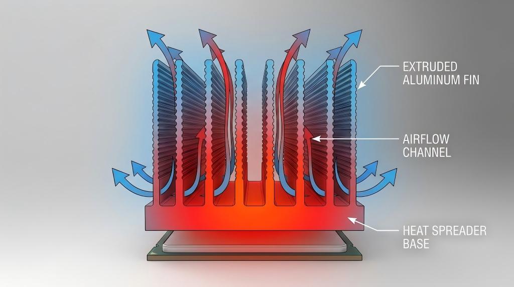
The goal of any heat sink is to minimize Thermal Resistance (Rth), measured in °C/W. The lower the resistance, the easier heat flows from the junction to the ambient air.
Natural vs. Forced Convection
The design geometry depends entirely on the airflow:
• Natural Convection (Passive): Requires wider fin spacing (typically >6mm). If fins are too close, the boundary layers of the still air overlap, creating a ‘choke point’ where air cannot rise, stalling the cooling effect.
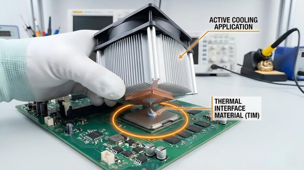
• Forced Convection (Fan Cooled): Allows for dense fin stacks (spacing <3mm). The high static pressure of the fan forces air through the tight gaps, stripping heat away via turbulence.
Fin Efficiency
A taller fin adds more surface area, but there is a point of diminishing returns. As heat travels up a tall, thin fin, the tip becomes cooler than the base. If the fin is too tall and thin, the tip does almost no work. This is known as ‘Fin Efficiency.’ Optimizing this thickness-to-height ratio is critical for material savings.
Design Logic: High Aspect Ratio Fins in Aluminum Profiles
The ‘Aspect Ratio’ in extrusion is the ratio of the fin height to the gap width between fins. High aspect ratios provide massive surface area in a small footprint, but they are a nightmare to manufacture.
The Extrusion Challenge
For standard 6063 aluminum, the maximum extrusion aspect ratio is typically 8:1 to 10:1. Pushing aluminum through a die with very thin, deep tongues requires immense pressure. If the ratio is too high, the steel die tongue will snap.
Anrele utilizes specialized high-pressure extrusion presses and proprietary die designs to achieve ratios up to 15:1 for specific high-performance applications. For designs requiring even higher density, we recommend consulting our engineering team about Skived Fin or Bonded Fin alternatives.
Material and Alloy Selection (6063 Thermal Conductivity)
Not all aluminum is created equal. The alloying elements that make aluminum strong (like Copper in 2000 series or Zinc in 7000 series) actually degrade thermal conductivity.
Why 6063 is King
• AL 6063-T5: Thermal Conductivity ~201-218 W/(m·K). This is the standard for heat sinks. It offers high extrudability and good surface finish.
• AL 6061-T6: Thermal Conductivity ~167 W/(m·K). While stronger structurally, it is roughly 20% less efficient at moving heat. Use 6061 only if the heat sink serves a structural load-bearing role.
The difference in thermal performance is significant for high-power applications like IGBT cooling. For related high-power electrical components, check our Aluminum Terminal Connectors.
Surface Treatment: Does Black Anodizing Help Heat Dissipation?
This is the most common question we receive at our Service Department. The answer lies in the physics of radiation.pneumatic automation components).
The Emissivity Factor
• Raw Aluminum: Emissivity (ε) ≈ 0.05. It reflects heat back inside.
• Black Anodized Aluminum: Emissivity (ε) ≈ 0.85. It radiates heat away effectively.
The Verdict:
In a Forced Convection (fan-cooled) system, convection dominates, and the color makes little difference (<5% improvement). However, in a Natural Convection (passive) system, radiation accounts for up to 25% of the total cooling. In these cases, Black Anodizing significantly improves performance.
Common Industrial Applications
Anrele profiles are found in critical infrastructure globally.
• LED Drivers: High-wattage LED lights require massive surface area to keep the junction temperature below 85°C.
• Inverters (VFDs): Variable Frequency Drives generate kilowatt-level waste heat. Large extruded profiles form the back chassis of these units.
• Automation Controllers: PLCs and CPUs in factory floors need passive cooling to avoid fan failure risks. (See our related
Conclusion: Custom Thermal Solutions for Reliability
Thermal management cannot be an afterthought. It dictates the form factor, the lifespan, and the reliability of your electronic product. While off-the-shelf profiles exist, high-performance applications often require custom extrusion to optimize the fin geometry for the specific airflow available.
At Anrele, we bridge the gap between thermal simulation and mass manufacturing. Whether you need a simple extruded comb or a complex cross-cut active cooler, we have the die capabilities to deliver. Visit our About Us page to learn more about our quality control standards.
FAQ: Common Technical Questions
1. How does fin spacing affect heat dissipation?
Tighter spacing increases surface area but increases air resistance (pressure drop). For natural convection, use wider spacing (>6mm). For forced air, use tighter spacing (<3mm) matched to the fan’s static pressure curve.
2. Is anodizing beneficial for heat sinks?
Yes. Besides corrosion resistance and electrical insulation (dielectric strength), anodizing increases surface emissivity, boosting radiative cooling by up to 20% in passive applications.
3. What is the maximum width for extruded heat sinks?
This depends on the press size. Anrele can extrude profiles up to 600mm wide using our large-tonnage presses. For wider requirements, we use Friction Stir Welding to join multiple profiles.
4. Can Anrele manufacture skived fin heat sinks?
Yes. When the required fin density exceeds extrusion limits (Aspect ratio > 15:1), we use Skiving technology, which shaves fins directly from a solid block, allowing for extremely thin and dense fins.
5. Comparison: Extruded Aluminum vs. Die Cast Aluminum heat sinks.
Extruded (6063) has 2x higher thermal conductivity than Die Cast (A380) aluminum (~200 vs ~100 W/mK). Extrusion is superior for thermal performance; Die Casting is better for complex 3D shapes and lower unit cost in high volume.
6. How do I calculate the thermal resistance needed?
Formula: Rth = (Max Component Temp – Max Ambient Temp) / Power Dissipated. Example: If your chip maxes at 85°C, ambient is 45°C, and it generates 20W, you need a heat sink with Rth < (85-45)/20 = 2.0 °C/W.